
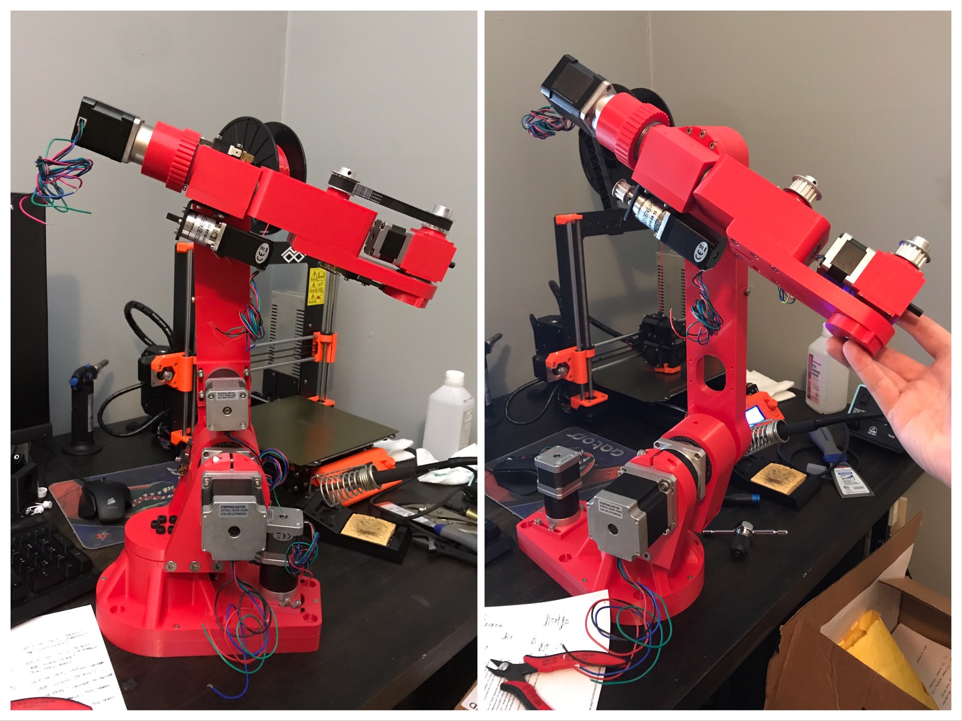
The photo on the left shows the robot rotated 180deg on the base (for storage). The right shows the robot in a partially assembled state.
I purchased the CAD (SolidWorks) files from Chris’s website so I could make some design modifications and then 3D print. I wanted to be able to export high-res STLs, so curved surfaces were curved rather than triangulated. I printed everything on my Prusa i3 MK3 (8” square build surface) with IC3D Red PET-G. All in, not considering reprinting any parts, it was just north of 70 hours of print time and under 2kg of filament.
Maybe the most visible design modification is at the base. I integrated the base and the J1 Turret, as well as the support ribs. This took the longest to print, at around 15 hours.
Due to the build surface constraint, I had to cut the J2 arm in half. For increased rigidity, I made the walls taller, similar to the supports Chris recommends when printing. I made some overlaps and printed a separate, bolt-on stringer to tie them together. It’s still a little wobbly, so I may revisit the design.
The modification with maybe the most design work is with the J5 actuation. I changed from the lead-screw-driven system to a bevel-gear-driven system. Initial (no load) testing shows pretty good prospect. By tensioning the belt, the J5 extended arm is slightly bent (it’s plastic...), so I may revisit this and go to a more direct-drive system. But for now I’m happy with how it’s working.
By changing to the bevel gear drive, I used a geared stepper, which sticks out the back of the J4 arm further. To utilize this space, I incorporated the J4 hub into the J5 motor mount.
For the J5 drive pivot on the J6 assembly, I had a hard time getting enough torque on the J5 drive pulley set screw without cracking the plastic. I modified the whole J6 design for ease of printing (modular instead of all-in-one) and used the leftover 8mm keyed shaft from J3 to fix the pulley. So far so good!
As for the electronics...that’s the next part of the fun. I plan to make a custom PCB that acts like a shield for the Arduino Mega. It will have screw terminals for the motor driver control wires, as well as for external IO. I’ll also include 2 DC-DC step-down converters to take the 24V from the power supply and output 12V for the Arduino and 5V for the RPi (see next paragraph). That way I can eliminate the 5V power supply. This concept needs validation, so I’ll update this post once I get it sorted out.
For actual control, I’ve modified the AR2 software to work on the RaspberryPi. I’m planning to use an RPi Zero W. I have it set up as a wireless access point, so I can access the GUI with a tablet via the free VNC Viewer app (android and iOS). Initial testing shows good prospect, but I need to validate that the RPi can handle the processing. If it works, I’ve got a headless unit - no Windows computer required!
That’s all for now, I’ll continue to update this post as I make more progress. Let me know if you have any questions!
-Zach

Nice work. Its awesome to see what you have done. Thanks for posting this. Please keep us updated on your progress. I’ve had a number of people asking about adapting the software for raspberry pi - if you could post a how to, a lot of people would be very interested. Thanks again.

Nice work!
Hi Zach,
Thank you very much for porting the program to RPI.
I just tried to use your version of the control software, but I have an issue:
when I want to calibrate one axis at a time (J1 for example) then the axis moves to limit switch, then waits for something forever. Running the AR2.py from console and hitting Ctrl +C I see that at line nr. 962 (calvalue = ser.readline()) is the last line executed.
I can move axes on "Main Controls" tab without problems
Also, no issues when I use the program from Windows.
Do you have any ideas, what could cause that behaviour
BTW, I had to change the serial speed in the RPI version to 115200, because that's the default speed of Arduino.
Best regards: Janos
https://anninrobotics.com/wp-content/uploads/2025/07/3D-Printed-AR2α_3.avif
I got the boards in yesterday and started assembling them tonight. There are some tight fits, which I’ll address in the next version. All of the drivers are mounted, the 2 buck converters are on the back (nested between the board and the Arduino), and I made a custom USB-B to micro-USB cable to jump between the Pi and the Arduino. I‘ll have to finish assembly and then test it out another day. Stay tuned!
https://anninrobotics.com/wp-content/uploads/2025/07/3D-Printed-AR2α_4.avif
Alright friends, sorry for the long radio silence. Just wanted to give a quick update...
While I’m still in the process of developing the ShushEngine, I’ve got a revised driver board/Arduino shield I want to try out. This picture is pretty low-res, but maybe you’ll be able to pick up on a couple things.
It uses the TMC5160 SilentStepStick breakout boards, which still uses Step/Dir. So it should still work with Chris’s original software! Next, I’ve got a jumper toward the top of the board, which allows you to pick “MEGA” or “DUE”. That’s right, I’m going to try to make it work with the DUE. I’m not 100% sure it'll work, because I’ve never used a DUE, but I’ll give it a shot. The jumper basically selects between 3.3V and 5V logic. The TMC5160s can work with either. And the board keeps the 3”x100mm size from the last version (not sure why I mixed units on it, but whatever). I’ll keep everyone posted on how this works. If it does, it’ll save a TON of space.
Wow, so nice. The RPi + Arduino looks like a great combination. I'm thinking of a carrier board too (just posted in my build) but this is clearly a good way to go.
Did you have to do lots of filtering on your buck converters? I'm always a little leary of powering stuff off the same supply as the steppers (I've fought with this on my home CNC machine), finally ended up with a separate logic supply. The AR2 has much smaller steppers, perhaps there is less to worry about.
You got me thinking; I should consider putting a RPi on my carrier too 🙂
/Mitch.

Wow, you're doing a huge job.
My English is not very good, there are things that I have not understood well. With your Shusengine, what do you do is load the arduino control into a RPi? Do you eliminate arduino from the control part, as well as the drivers that Chriss uses in your project, no? I was talking to him about the possibility of using Arduino Due 32 bits and tmc drivers like those used in 3d printers. With the Shusengine theme, when loading the control in the RPi, would you also load the Chris control software for PC in the same RPi or should you continue using a PC to control the AR2?
I'm waiting to start the construction of AR2 printed on PET-G too, you had to give horizontal expansion (I use CURA) to improve the tolerances of the bearings? Greetings and great work! I look forward to your progress.
Another part of the project in the works...
Hi, Everyone!
I haven't posted in a while, but if anyone is following this and is wondering about how to get the software to work on their Raspberry Pi, @Chris Annin pulled my code/documentation into his repository:
Updates:
I'm still working through my somewhat-modified 3D printed AR2 robot, but have recently shifted focus to the stepper drivers. In @Max Favre's build log, we discussed using Trinamic's motion control drivers for the stepper motors. There's a product on the market called SlushEngine, which is an open-source project by Roboteurs - you can check out their website and GitHub repo here:
https://github.com/Roboteurs/slushengine. This product seems like a great option, but at a pretty steep price, especially compared to the drivers @Chris Annin picked from StepperOnline.
I'm working on making a driver system similar to the SlushEngine, but with TMC5160 drivers by Trinamic. They offer a lot of impressive functionality, but I won't go into all of that in this post. They offer a small form-factor, as well as high amp-per phase current. Additionally, they offer 256 microsteps per step, which gives them very smooth and precise operation. One of the best selling points for this application, which the SlushEngine also offers, is direct positioning. As in, the motion controller is built into the chip, and you only have to give it a position command and it does all the hard work internally. That means no step-direction, no Arduino required, and no real-time OS (e.g. RPi Raspbian OS).
I've modified the SlushEngine project for the TMC5160s, but it's very much a work in progress. It works entirely (and exclusively) on the Raspberry Pi, which aligns with my goal for the project - drive the AR2 with only a Raspberry Pi, preferably the $5 RPi Zero W. My milestone tonight was getting the library at a point where a very short Python script would make the motor run 5 rotations (arbitrarily picked) back and forth.
While I want to tap into the functionality of the drivers more, I'm going to start a parallel path of adapting my already published RPi code with this new driver. Overall I think the AR2 software, written in Python, will work great with these drivers. The drivers have inputs for limit switches, so the home position can be recorded by the driver. This should greatly simplify the homing scheme.
One of the trickiest parts I believe I will deal with is syncing all the motors. Meaning getting all the motors to run the same amount of time, regardless of how many steps they have to take. There's no problem getting them all to start at the same time but for precise and complex motions, having some sort of CNC-esque logic will make this a lot better.
Overall, I'm quite impressed by these drivers, and hopefully I can get this library matured and integrate it into the AR2 software quickly.
Another important piece of the pie is obviously the driver circuit board. Now that I have a working prototype with Trinamic's pre-built breakout board, I will begin to tackle designing the PCB, sourcing the parts, and assembling it all. I'm not sure the price-point will get below the StepperOnline drivers, but it will hopefully be cheaper than the SlushEngine.
Since I'm building off the SlushEngine project, instead with Trinamic's famed silent stepper drivers, I'm calling the project "ShushEngine". I'm bad at coming up with names, so let me know if anyone has any better ideas. You can find my GitHub repo where I'll be constantly updating the code at:
Here's a quick video showing the motor spinning with the code written behind it.
that sounds great. thank you.
I got it wired up and it works! I’m ecstatic. I tried to upload a video to YouTube, but there was an error. I’ll try again later. @Chris Annin, I’ll get to work on the how-to
Update on the RPi AR2 controller... I’m planning to test with the robot today, and if all works I’ll put together a tutorial.
I've never used GitHub before, so I'm still trying to learn how it all works. But I made a fork of the AR2 project and uploaded the board Gerber files as well as images of the board layout:
I ordered my boards through JLCPCB.com, and got 10 boards for $20 shipped to Ohio, USA.
If anyone has any questions, let me know!
its nearly the same board with much faster processor - it uses an ARM processor instead of AVR so it runs at 3.3v which is a pain since most stepper drivers are 5v.
 GITHUB.COM
  ROBOTEURS.COM